How to detect if there someone is home or if the house is empty.
Prerequisite
- OpenWRT router
- MQTT server
- Something to interpret and display data (Node-RED, Home Assistant, Domoticz, OpenHAB, etc.)
On your OpenWRT router:
Install mosquitto-client. If you don't use encrypted communication use -nossl version.
opkg install mosquitto-client-ssl
Download presence_sensor script:
wget -O /usr/bin/presence_report https://github.com/dersimn/owrtwifi2mqtt/raw/master/presence_report
make it executable:
chmod u+x /usr/bin/presence_report
Now you can check if it works. Run command:
root@OpenWrt:~# /usr/bin/presence_report event 192.168.1.8
presence_report, mode: event, MQTT server: 192.168.1.8
Change 192.168.1.8 to address of your MQTT server. Turn WiFi on one of your devices (my was e6:6a:ca:c8:38:e6).
root@OpenWrt:~# /usr/bin/presence_report event 192.168.1.8
presence_report, mode: event, MQTT server: 192.168.1.8
Mac: e6:6a:ca:c8:38:e6 did del
Mac: e6:6a:ca:c8:38:e6 did new
as you can see there my device "left" (del) and connect (new) to Wi-Fi.
Press Ctrl-C to stop test.
To start this every time router boots I've added this line:
(/usr/bin/presence_report event 192.168.1.8 >/dev/null 2>&1 )&
to /etc/rc.local file. Of course before "exit 0".
Using data
You can subscribe to "owrtwifi/status/#" topics to receive messages in topic like this:
owrtwifi/status/mac-e6-6a-ca-c8-38-e6/event
and payload del or new.
They are also messages in topic
owrtwifi/status/mac-e6-6a-ca-c8-38-e6/dhcp-name
and name of your device in payload.
I'm using Node-RED and check every device like this:
context.devicescount=0;

if (!context.hasOwnProperty("devices")) {
    context.devices={};
}

if (msg.topic === "owrtwifi/status/mac-e6-6a-ca-c8-38-e6/event") {


    if (msg.payload === "new") {
        context.devices.PhoneNo1 = 1;
    }
    if (msg.payload === "del") {
        context.devices.PhoneNo1 = 0;
    }
}
// repeat above to all of your mobile devices
if (msg.topic === "owrtwifi/status/mac-00-11-22-33-44-55/event") {


    if (msg.payload === "new") {
        context.devices.PhoneNo2 = 1;
    }
    if (msg.payload === "del") {
        context.devices.PhoneNo2 = 0;
    }
}


let values = Object.values(context.devices);

values.forEach(function (value,index) {
    if (value == 1) {
        context.devicescount+=1;
    }
    return null;
});

if (context.devicescount>0) {
    node.send({payload:{"devices":context.devicescount},topic:"mydevices"});
}
else {
    node.send({payload:{"devices":context.devicescount,"house is empty":1},topic:"mydevices"});
}
Maybe it's not the best way, but it works for me.
The most important value is devicescount - the house is empty if equal to zero.
Of course this method cannot distinguish if you are in home or you just forgot your phone. It's obvious, but I want to be sure you know this too ;-)
There is easy way to control lights using PIR (Passive Infra Red) it looks like this:
![]()
As usually message from MQTT broker is translated to JSON, then I use switch to filter-out message from PIR (in my case AA0446). I sent "On" and 5 minutes later "Off" to template
{
  "idx" : 25,
  "command" : "switchlight",
  "switchcmd" : "{{payload}}"
}
Finally full message is sent to domoticz/in topic.
Complete code.
How to switch light using 3 channels 433MHz switch. It's very simple:
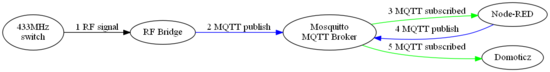
1 RF signal
My 3 button 433MHz switch sends 3 codes:

- 672BE2- left button
- 672BE8 - center button
- 672BE4 - right button
2 MQTT publish
I set up RF Bridge to send MQTT messages like this (center button):
{
  "RfReceived" : {
    "Sync" : 7840,
    "Low" : 250,
    "High" : 780,
    "Data" : "672BE8",
    "RfKey" : "None"
  }
}
to topic:
tele/DVES_B2EFB9/RESULT
Domoticz needs to get mesage with topic:
domoticz/in
with payload like this:
{
  "idx" : 22,
  "command" : "switchlight",
  "switchcmd" : "Toggle"
}
We need to translate:
![]()
3, 4 and 5 message translation
Mosquitto and Node-RED are deployed using Docker on same machine:
docker run -it -p 1883:1883 -p 9001:9001 --name mosquitto \
-v mosquitto:/mosquitto/config -v mosquitto:/mosquitto/data \
-v mosquitto:/mosquitto/log eclipse-mosquitto

docker run -d -p 1880:1880 --restart=always  \
--log-opt max-size=10m --log-opt max-file=5 \
-v node-red-data:/data --name nodered \
--link mosquitto:broker nodered/node-red-docker:slim
You can see that I've link mosquitto container as broker.
The switch node splits messages depending on msg.payload.RfReceived.Data, and change node set properties (idx, command and switchcmd)
![]()
Here you have complete Node-RED code.
Finally Domoticz tuns the light!
Of course you have to have set up Domoticz first.
Recently I've found interesting device - it is WiFi to 433MHz gateway.

I've used FlashESP8266 to flash sonoff.bin (6.2.1).
Connect 3.3V USB-RS232 interface to J2 (you won't need 5th - SDA - pin).
To program you have to set S2 switch to OFF position.
 position")
As You can see it is in ON (normal) position.
Future reading:
- Sonoff RF Bridge w/ MQTT & Home Assistant
- thehackbox.org/tasmota
- Modified External GPIO Jack for Sonoff RF Bridge R2
- OpenMQTTGateway
Three chanel 433MHz relays - it uses specific protocol:
I would like to have light with switch (it should work even without domoticz) but I would like to use power of domoticz also ;-)
In ESP (ESP6) I've devices:
- Switch input:
- name: button
- IDX: 25
- 1st GPIO: GPIO16
- Pull UP: set
- Inversed: not set
- Switch Type: Switch
- Switch Button Type: Push Button Active Low
- Send Boot state: not set (you can set it if you want)
- Send Data: set
- Switch input
- name: okno
- IDX: 23
- 1st GPIO: GPIO16
- Pull UP: set
- Inversed: set
- Switch Type: Input
- Switch Button Type: Normal Switch
- Send Boot state: not set (you can set it if you want)
- Send Data: set
- Switch input
- name: zlew
- IDX: 24
- 1st GPIO: GPIO12
- Pull UP: set
- Inversed: set
- Switch Type: Input
- Switch Button Type: Normal Switch
- Send Boot state: not set (you can set it if you want)
- Send Data: set
In domoticz I've three "On/off" switches:
- "ESP6-okno"
- IDX: 23
- On Action: http://esp6.lan/tools?cmd=GPIO,14,0
- Off Action: http://esp6.lan/tools?cmd=GPIO,14,1
- "ESP6-zlew"
- IDX: 24
- On Action: http://esp6.lan/tools?cmd=GPIO,12,0
- Off Action: http://esp6.lan/tools?cmd=GPIO,12,1
- "ESP6-both"
- IDX: 25
- On Action: http://esp6.lan/control?cmd=event,zapal
- Off Action: http://esp6.lan/control?cmd=event,zgas
ESPeasy Rules:
On button#Switch do
  if [button#Switch]=0.00
    event zgas
  else
    event zapal
  endif
endon

on zapal do
  gpio,12,0
  gpio,14,0
endon

on zgas do
  gpio,12,1
  gpio,14,1
endon
As you can see when ESP6-both is changed I call "rules" from ESP
You can read more about rules in Rules Tutorial.
I tried to monitor my flat using old phone as web camera (should be replaced with IP camera). It's quite simple using one of many Android apps (IP Webcam by Pavel Khlebovich in my case).
Since I do not have public IP I had to use OpenVPN to my home network:

|
My phone/camera has address 192.168.1.11 (Home LAN network). To have access to it from Internet, I had to add this to cameras.conf file (in /etc/httpd/conf.d directory):
<Location "/cam1">
        ProxyPass "http://192.168.1.11:8080/"
        ProxyPassReverse "http://192.168.1.11:8080/"
</Location>
Now I can see what is happening typing http://cameras.jaqb.gda.pl/cam1 in web browser.
What is worse anyone can see. To protect my own privacy I've added authentication, so whole file looks like this:
<VirtualHost *:80>
<Location "/cam1">
        ProxyPass "http://192.168.1.11:8080/"
        ProxyPassReverse "http://192.168.1.11:8080/"

        AuthType Basic
        AuthName "Acess to my first camera"
        AuthBasicProvider ldap
        AuthLDAPURL "ldap://localhost/dc=jaqb,dc=gda,dc=pl" NONE
        AuthLDAPBindDN "cn=administator,dc=jaqb,dc=gda,dc=pl"
        AuthLDAPBindPassword typeyourpasswordhere
        AuthLDAPGroupAttribute memberUid
        AuthLDAPGroupAttributeIsDN off
        Require ldap-user jakub
</Location>

</VirtualHost>
Now only user jakub (me ;-) can have access.
If you want to calculate device value you have to fill "Formula" field, ie:
%value%*1
which of course returns value multiplied by 1 ;-).
In my case I had to calculate voltage measured by 1:2 divider and 1:3.3 divider, so my formula was:
%value%/1024*3.3*2
the value is divided by 1024 because ADC has 10 bit resolution.
This is example how to use ESP Easy rules on ESP Witty (ESP8266). It shows timer, events, and assigning value to "variable".
The pins are connected as below:
- GPIO4 - Push Button
- GPIO12 - Green LED
- GPIO13 - Blue LED
- GPIO15 - Red LED
One device is set to Switch input and it is named button with "1st GPIO" set to GPIO-4. You cannot have variables, but You can have dummy device to store values. So I've created Dummy Device with name zmienna and set "Value Name 2" to indeks. In this example this dummy device is "Task" 3.
How it works?
If you push button the one LED is turn on for 1 second. If you push it again the next LED is turn on.
On button#Switch do
  if [button#Switch]=0.00
    event zgas
    // increment task 3, value 2
    TaskValueSet,3,2,[zmienna#indeks]+1
    event zapal
  endif
endon

// turn on one LED
on zapal do
  timerSet,1,1 // timer 1, one second
  if [zmienna#indeks] > 2
    // reset counter
    TaskValueSet,3,2,0
  endif
  if [zmienna#indeks] = 0
    gpio,12,1 // Green
  endif
  if [zmienna#indeks] = 1
    gpio,13,1 // Blue
  endif
  if [zmienna#indeks] = 2
    gpio,15,1 // Red
  endif
endon

On Rules#Timer=1 do
  event zgas
endOn

// turn off all LEDs
on zgas do
  gpio,12,0
  gpio,13,0
  gpio,15,0
endon
I had a problem with Domoticz and switches.
I've ESP8266 module (with ESP Easy v.120) and relay (SSR) - it's very simple to get it work using web interface.
I would like to have some kind of switch not to have use phone to turn on the light. My solution it's not so simple I think it can be done better.
My ESPEasy module has address 192.168.1.7, SSR is connected to GPIO12 and touch sensot is connected to GPIO14. It has configured "Protocol" as "Domoticz HTTP". The "touch" switch is defined in ESPEasy as:
- Device: "Switch input"
- IDX / Var: 10 (Idx from Domoticz)
- 1st GPIO: GPIO14
- Type: "Switch"
- Switch Button Type: "Normal switch"
- Send Data: On
I didn't define relay connected to GPIO12 - it is set directly from domoticz as described below.
My domoticz has address 192.168.1.8. I defined "dummy" hardware with two "switches":
- "light" - it has defined "On action": http://192.168.1.7/tools?cmd=GPIO%2C12%2C0 and "Off action": http://192.168.1.7/tools?cmd=GPIO%2C12%2C1
- "touch" - without any settings
Next I've defined new "Event" ("Lua", "Device"):
commandArray = {}

if (devicechanged['touch']=='Off') then
    if (otherdevices['light']=='Off') then
--        print ("wlaczam");
        commandArray['light']='On'
    else
--        print ("wylaczam");
        commandArray['light']='Off'
    end
end

return commandArray
Remember to set "Event active" checkbox.
Now I can use both web interface and physical switch to turn on/off the light.
I had to use Windows machine, if you use Linux you will need esptool and flash script for Linux.
First of all you have to download ESP Easy firmware, i.e. version R120. and unzip it to some folder (I've used C:\Users\username\Downloads\ESPEasy_R120)
If you have some ESP8266 module (they have different names, you have to search: ESP8266, Witty, NodeMCU or Lua) with USB interface the only think you have to do is connect to PC or you have to have serial to USB adapter.
After connect you have to check (virtual) serial port number. In my case COM3.
In first step I used smallest image:
cd C:\Users\username\Downloads\ESPEasy_R120
esptool.exe -vv -cd nodemcu -cb 115200 -cp COM3 -ca 0x00000 -cf ESPEasy_R120_512.bin
When you use putty connect to COM3 (115200 8N1) you will see log. Something like this:
WIFI : No SSID!
 INIT : I2C
 INIT : Boot OK
 INIT : Normal boot
Now you have to connect to WiFi network named ESP_0, password can be configesp. I've used Android phone, so I've been automatically redirected to configuration page where I can provide SSID and password to my WiFi. In console you can see:
WIFI : Connecting... 1
WIFI : Connected!
Then you have to disconnect from ESP_0 network and connect again. After this you will see:
FLASH: Settings saved
now you have your module configured to your WiFi network.
After this I've checked that my module (Main, Flash Size) is 4MB version and flashed them again using another image:
cd C:\Users\username\Downloads\ESPEasy_R120
esptool.exe -vv -cd nodemcu -cb 115200 -cp COM3 -ca 0x00000 -cf ESPEasy_R120_4096.bin
I didn't notice any changes so I thing 512kB image is enough.
Add comment